
At Codium, we have a soft spot for problems that get solved with three capacitors worth a few cents, rather than a full board re-route. Here's a good example.
On two BLE boards built around Nordic Semiconductor's nRF54L, we recovered between 8 and 14 dB of transmit power. Without touching a single active component. Just by retuning three capacitors, a few tenths of a picofarad, on the antenna matching network.
The starting point is utterly mundane: you take the "off-the-shelf" matching network from the manufacturer's documentation, route the board, flash a test firmware, measure... and the power isn't there. Not slightly off — essentially missing. Here's how we recovered the missing decibels, and why this kind of unpleasant surprise happens far more often than you'd think.
The matching network: three inductors, three capacitors, two jobs
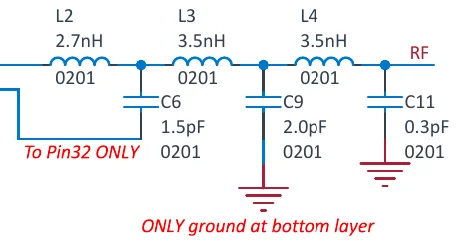
Between the nRF54L's power amplifier (PA) output and the antenna, Nordic recommends a small network of three inductors and three capacitors. Tiny on the schematic, but it does two essential things at once.
First, it matches the impedance of the PA to the 50 Ω line, so the power actually goes toward the antenna instead of reflecting back. Second, it filters harmonics: it's a low-pass that attenuates the 2nd harmonic (4.8 GHz) and the 3rd (7.2 GHz) — something you can't ignore if you want to pass certification testing.
Why the manufacturer's recipe is never quite enough
The values Nordic provides are calculated for their own reference board. On your PCB, everything is slightly different: the routing isn't the same, neither is the spacing between components, nor the layer stack-up, nor the number of vias.
At 2.4 GHz, these details — which you'd dismiss as trivial elsewhere — stop being trivial. A few extra millimetres of trace behave like a small additional inductance. One more via, same story. The impedance seen by the PA shifts slightly, and the manufacturer's "ideal" network simply isn't ideal anymore on your board.
The concrete result: part of the power is lost before it even reaches the antenna. Range drops, the link becomes more fragile in a noisy environment, and the battery works for nothing to compensate.
Our method: measure, adjust, repeat
There's nothing magic about the method — it's deliberately hands-on. We program the chip to emit a continuous carrier at a fixed frequency, set to +7 dBm (the nRF54L's maximum power in a QFN package; the CSP version goes up to +8 dBm). We then measure, with a spectrum analyzer, the power actually available at the output.
As long as the reading stays far from the expected +7 dBm, we adjust the network values and start again. Nordic states you should be able to reach the programmed power within ±2 dB: that's the target we set ourselves.
The numbers, on the spectrum analyzer
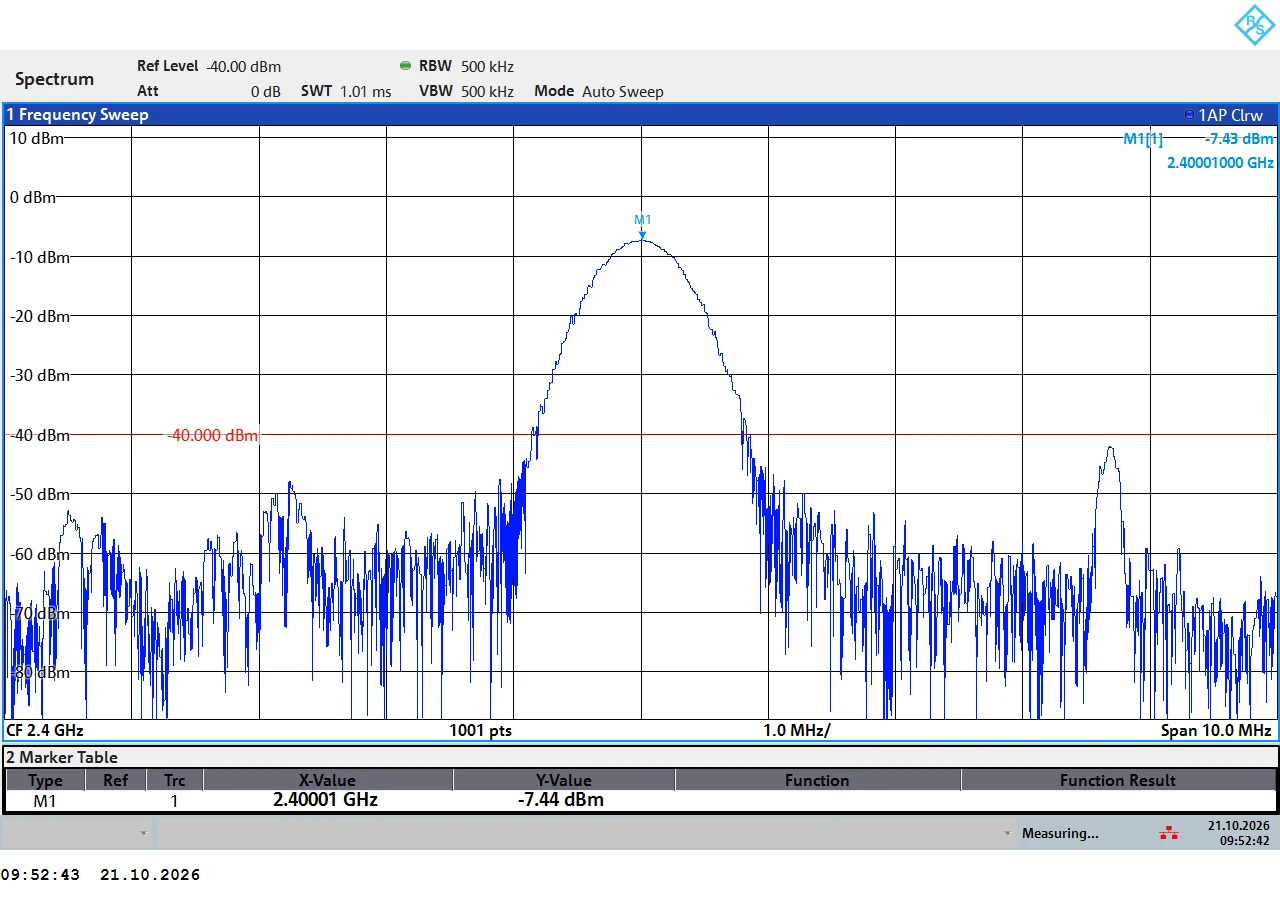
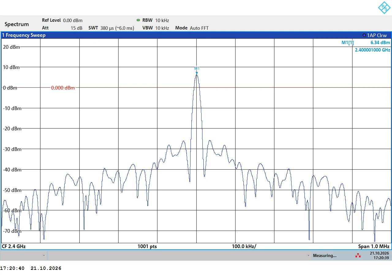
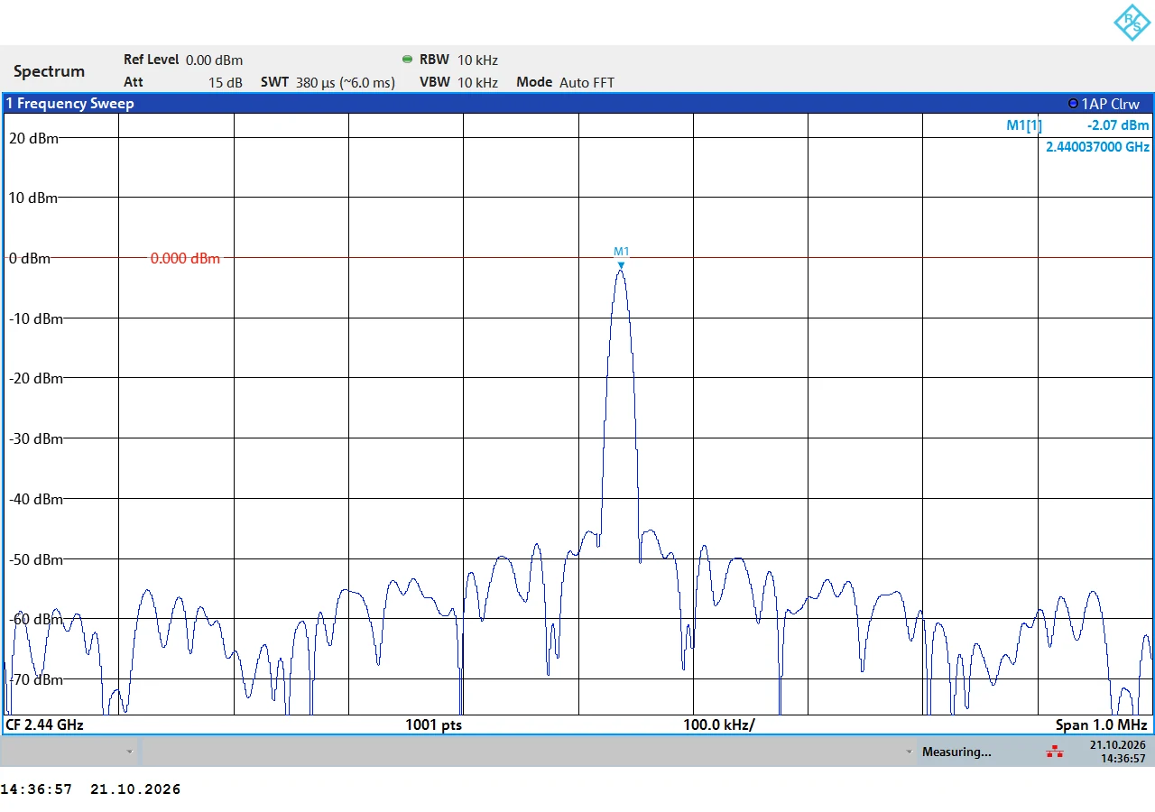
After optimisation, both boards come out at just over +6 dBm — right in the range Nordic announces.
| Board | Before (Nordic network) | After (Codium network) | Gain |
|---|---|---|---|
| Board 1 | −7.4 dBm | +6.3 dBm | ≈ 13.8 dB |
| Board 2 | −2.1 dBm | +6.2 dBm | ≈ 8.3 dB |
Board 1 — the worst starting point
Board 2 — already decent, but far from the chip's potential
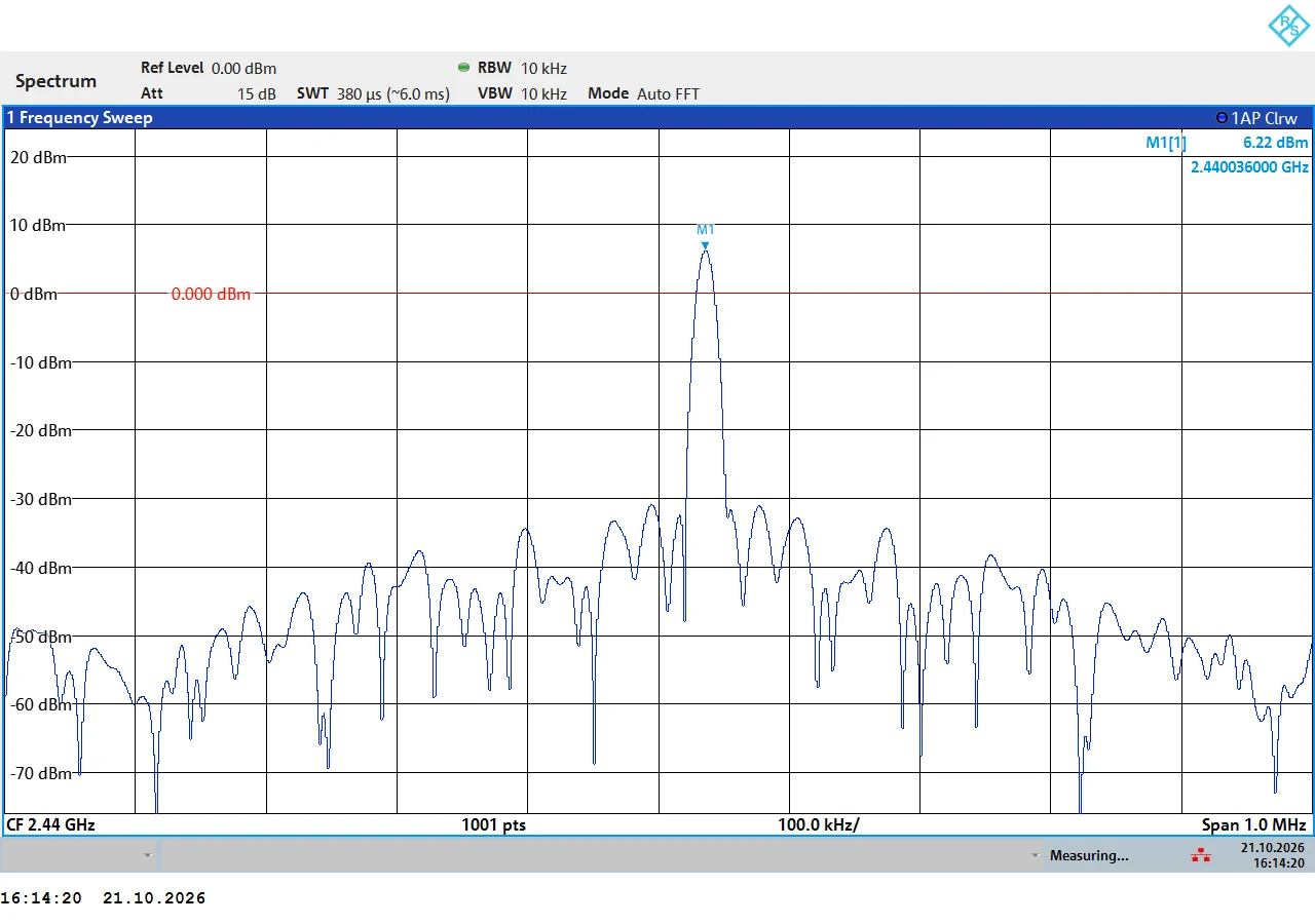
To put these numbers in perspective: 8 dB is roughly 6 times more radiated power. 14 dB is roughly 24 times more. In free space, that theoretically translates to 2.5 to 5 times the range.
We also checked that the matching held across the whole BLE band, not just at the measurement point: several readings at different frequencies confirm the network stays effective across the band, not only where we aimed the test.
The tuning we kept
The inductors didn't move a single nanohenry. Everything happened on the three capacitors to ground.
| Position in the network | Nordic value | Codium optimised value |
|---|---|---|
| Chip-side capacitor | 1.5 pF | 0.8 pF |
| Centre capacitor | 2.0 pF | 0.7 pF |
| Antenna-side capacitor | 0.3 pF | 0.5 pF |
| Series inductors | 2.7 / 3.5 / 3.5 nH | unchanged |
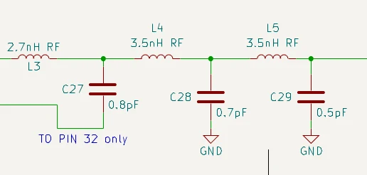
A few tenths of a picofarad, an identical bill of materials cost, and a board that finally uses the full potential of the chip it carries.
What to take away
"A matching network is validated on the real board, not just in the datasheet. Every PCB has its own routing, so its own optimal tuning."
— Pierre Belloche, Electronics engineer, RF specialist, CodiumFor a BLE product, these recovered decibels translate into something very concrete: more range, a more robust link in a noisy environment, and, at equal range, the option to lower transmit power to save battery.
At Codium, RF and embedded engineering live under the same roof, in Langres: we design the board, route the matching network, and measure and tune it ourselves before taking you to an accredited lab for certification. Developing a connected product in BLE, DECT NR+, LTE-M or LoRa? Let's talk.